Building A Supply Water Quality Testing System
Posted on October 17, 2021 • 8 minutes • 1533 words
Table of contents
The project is called “Real-time Remote Based Supply Water Quality Testing System”. I, along with three other teammates: @mashiat , @rifat , @naeem worked on the project under the supervision of Dr. A.B.M Alim Al Islam.
The codes and libraries used in this project can be found in this repository .
Contents
- What Is It?
- The Working Principle
- The Components
- Making It Work
- Things I Wish I Knew Before
- Conclusion
- Important Resources
- References
What Is It?
Simply put, we built a device that reads the basic properties of water samples and checks whether it is safe for basic usage or not. We designed our first draft where we would monitor the water properties using different sensors and feed the data to a central monitoring unit. For the central monitoring unit, an ATmega32 micro-controller was used which read data from the sensors and determined whether the water quality was safe or not. We also added a communication module to notify the user whenever the water quality changes.
The Working Principle
The first step to knowing whether the water is safe or not is to check its quality parameters level. According to the Department of Public Health Engineering, Bangladesh , the standard level of water parameters are as below:
| Water Parameter | Standard Level |
|---|---|
| pH | 6.5 - 8.5 |
| TDS | 1000 mg/L |
| Turbidity | 10 NTU |
If the water quality deviates from these levels, it is not safe for use. That is when our unit would notify the user about the change. Since supply water can change anytime, our unit will keep on monitoring the water quality all the time. Upon finding out the value of water parameters, the unit will send a text message to the user’s phone number- notifying whether the water is safe or not.
What if there is no mobile network? We need to notify the user in some way, right? That’s why used a buzzer system to notify the user while the water parameters value would be shown in an LCDachieves.
Now that, we have established a working principle, let’s get the necessary pieces of equipment needed for the implementation.
The Components
Sensors
- Analog pH Sensor (DIY More PH-4502C)
- Analog TDS Sensor (Gravity TDS Meter)
- Analog Turbidity Sensor (Gravity SEN0189)
Communication Module
- SIMCom SIM900 Mini GSM module
Central Unit
- ATMEL ATmega32
Other Components
- 16x2 LCD display
- Active Buzzer
- USBasp Programmer
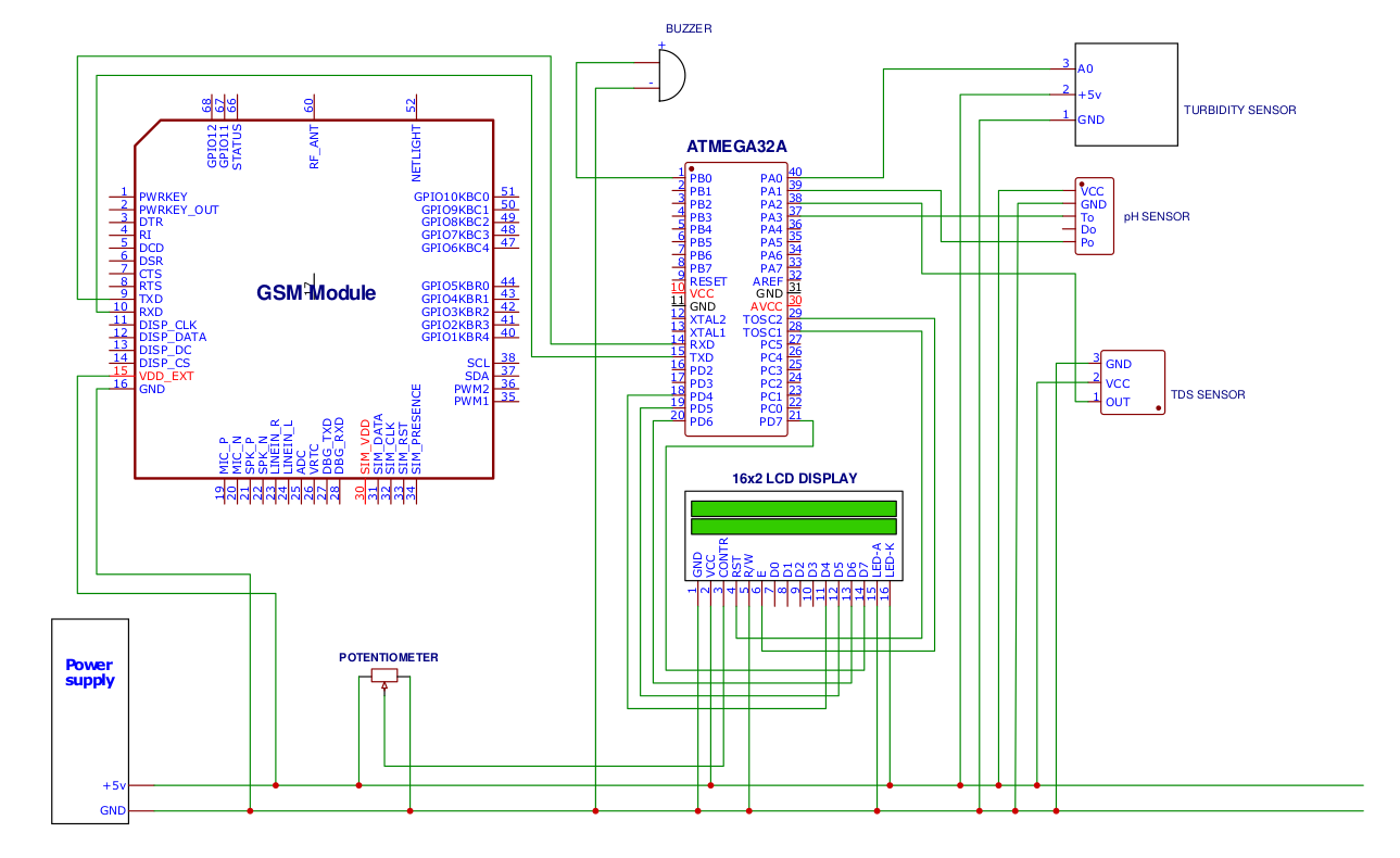
Circuit Diagram

Making It Work
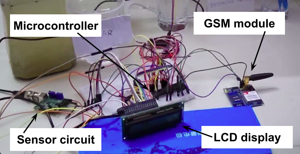
Now that we have all the components ready, let’s get to work. Since it’s just an implementation, we used breadboards for connecting the components.

Power Source
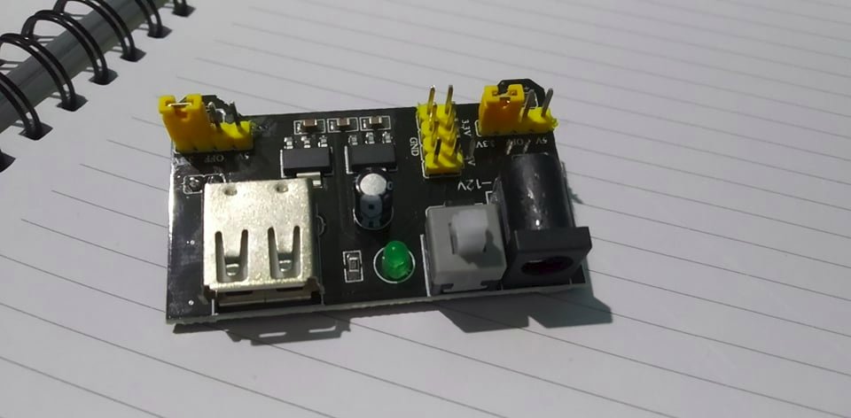
We found great hardware in the market- a breadboard power supply unit. It takes 12V DC input voltage and outputs 5V and 3.3V in different pins. What makes it more awesome is that it fits on the breadboard perfectly. We bought a 12V DC adapter to use with it- no extra hassle of using batteries.
LCD
Firstly, we connected our LCD with the micro-controller. To adjust the brightness of the text, a potentiometer was also connected. We used this library to connect our LCD with the AVR.
Getting the Sensors Work
Everything related to sensors was done by @mashiat . I still wonder how she was able to put it all together! Since I’m the one writing this blog, I am putting the working principle provided by her in the project report below-
pH Sensor
A pH sensor measures the pH level of the given solution. It provides 3 output pins. One for the analog output (Po), one for digital (Do), and one for temperature (To). Among these three, we will be using the analog output and the temperature output pins. The following formula was used to determine the pH value from the voltage-
ph_value = -5.7 * ph_volt + 21.34
Turbidity Sensor
A turbidity sensor measures the amount of light that is scattered by the suspended solids in water. As the total amount of suspended solids increases, the water’s turbidity level (haziness/cloudiness) increases. Word of advice, the turbidity sensor should never be fully drowned in water, only the light emitting-receiving part.*
The equation used for measuring the turbidity is-
turb_value = -1120.4 * turb_volt^2 + 5742.3 * turb_volt - 4353.8
Here, turb_volt is the output voltage found from the sensor pin.
TDS Sensor
We used the raw equations from Arduino’s GravityTDS.h library which computes TDS from EC (Electrical Conductivity). The temperature of the water is also needed to compute TDS which we took from the pH Sensor.
temp_val    = temp_volt/10.0
temp_coeff  = 1 + 0.02 * (temp_val - 25)
tds_coeff   = (133.42 * tds_volt^3 - 255.86 * tds_volt^2 + 857.39 * tds_volt) * 0.5
tds_value   = tds_coeff/temp_coeff
Here, temp_volt is the output voltage of the temperature pin of the pH sensor. Remember we said that we need temperature to determine TDS of water? This is where we apply it. tds_volt is the output voltage provided by the TDS sensor.
GSM Module
The module involved working with a VCC pin where a 5V voltage source was connected, a GND pin where the GND was connected, a TXD pin connected to the RXD pin of the microcontroller, and an RXD pin connected to the TXD pin of the microcontroller.
Since our project was remotely based, it required a system to send our sensors’ data to the user. To achieve that, we used a GSM module to send SMS containing the sensors’ data to the user. A SIM card was necessary to connect the module to the mobile network. The module used the achievesUART protocol to receive AT commands sent from the microcontroller.

And with that, our module is complete. By powering up the device, and submerging the sensors in water, we soon see the readings on the LCD. Upon the water quality changing, we get an SMS on our mobile phone.
Now, there are things I haven’t mentioned. We took readings from the sensors multiple times and used the mean value- to ensure correctness. And the user was notified only when the unit found a noteworthy change in the water parameters value.
Things I wish I knew before
Using Arduino For Testing
Arduino is one of the best things I have ever come across while working on this project. @mashiat’s Arduino Uno was a lifesaver whenever I had to test one of the new features of our project. Why is so? Because it is easier to operate an Arduino using their IDE and the hot-reload functionality. All I needed to do was plug the Arduino using a USB cable and write codes in the Arduino IDE. Then hitting ‘compile’ would just feed the code to the Arduino and I would be able to see the results quickly.
I discovered another hack while using the Arduino IDE. Getting the GSM module to work for the first time was a pain. I would have to write the AT commands to the AVR, burn it, start the system, and wait for the SMS to be sent to my phone. While using Arduino to master AT commands made the experience somewhat easy, I found another way to use Arduino as a command line to the GSM module.
#include <SoftwareSerial.h>
SoftwareSerial SIM900A(10,11);

void setup()
{
  SIM900A.begin(9600);   // Setting the baud rate of GSM Module
  Serial.begin(9600);    // Setting the baud rate of Serial Monitor (Arduino)
  Serial.println ("SIM900A Ready");
  delay(100);
}

void loop() { // run over and over
    if (SIM900A.available()) {
        Serial.write(SIM900A.read());
    }
    if (Serial.available()) {
        SIM900A.write(Serial.read());
    }
}
What the code above does is, binds Serial IO to GSM’s IO. Every time the code finds an input on my keyboard (Serial), it writes the input to the GSM module and vice versa. This small trick came in handy when I couldn’t find any TTL converter to buy.
The LCD Backlight Is Independent
We were almost at the end of our development and- that’s when we faced a new crisis. We weren’t getting any SMS from the GSM module. We tested the voltage at the terminal and found that it was still getting 5V- as required, but something was off. After a while of trial and error, we found out the problem. We disconnected the LCD from the power source and it was working again, we started getting SMS soon enough.
That is when we discovered that the LCD was drawing more power than we anticipated. As a result, the GSM module wasn’t getting enough current even though it was getting enough voltage. Previously, we tried using multiple power sources- connecting their grounds. But then some components weren’t starting and those which did start glitching soon. Then we found out the LCD backlight is independent of the rest of it. Soon we powered it using a 9V battery, and every single part of our whole unit was working perfectly again!
Conclusion
Among all of the departmental courses I came across in my academic life, this was one of the best. Before this course, I was someone who didn’t like hardware- but the project, the theory, concepts of it made me change my mind.
Important Resources
References
- DIY Ph Meter using PH Sensor
- Gravity TDS Sensor: Github Repo
- Gravity TDS Meter Introduction
- Turbidity sensor SKU SEN0189
- SIM900 AT Commands
Cover image from flaticon .

